Aerospace power systems leave little room for guesswork. A rack-mounted supply may sit behind a panel, yet its performance affects equipment stability, maintenance schedules, and available space. This guide to the 10 Best Aerospace Rack Mount Power Supplies for 2026 examines options through practical selection criteria, not headline wattage alone. Fit matters.
The comparison considers output capacity, input range, efficiency, cooling, protection features, and mechanical compatibility. It also looks at documentation and support, since clear specifications can make integration and servicing more predictable. An Aerospace Rack Mount Power Supply should match the load profile and installation environment, with enough margin for startup demand and future changes. Check connector layouts, airflow direction, mounting depth, and derating limits against the actual system requirements. Small details count.
No single model suits every aircraft, test bench, or ground-support rack. A compact unit may conserve valuable space but offer fewer expansion options. A higher-capacity model may provide headroom, yet bring added heat, weight, or cost. Those trade-offs are easy to underestimate. Specifications also cannot replace qualified engineering review, especially when a supply must work within a larger, tightly controlled power system. Treat this list as a starting point, and verify current manufacturer data before choosing. Some comparisons will remain imperfect because product configurations and availability can change. That is worth acknowledging. The goal is a clearer shortlist, grounded in measurable requirements and real installation constraints.
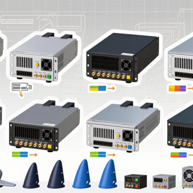
Aerospace rack-mount power supplies convert incoming electrical power into stable outputs for avionics benches, integration rigs, and ground-support equipment. Their job is not simply to provide the correct voltage. They must also handle changing loads, electrical noise, and heat inside tightly packed enclosures. A supply feeding a navigation unit, for example, may need clean rails while nearby equipment switches on and off.
The operating environment shapes the design. Rack airflow can be restricted, so technicians check fan direction, clearances, and inlet temperature rather than assuming the room is cool enough. Vibration, altitude, and electromagnetic compatibility may also matter, depending on whether the unit stays in a laboratory or travels with test equipment. Fit and connectors count. A secure mounting rail and clearly labeled outputs can prevent avoidable setup errors.
Not every rack supply is suitable for flight. Airborne use requires equipment and installation to meet applicable program requirements; a laboratory-rated unit should not be treated as flight hardware. Engineers typically review output regulation, protection behavior, monitoring signals, and service access against the actual load profile. One detail is easy to miss: a supply can pass a bench check yet struggle in a crowded rack. That gap deserves honest testing.
Aerospace rack mount power supplies must meet the needs of their specific aircraft or ground-support environment. Safety checks should cover electrical isolation, grounding, overcurrent protection, and thermal behavior. A unit may pass a bench test yet overheat in a tightly packed rack. Small details matter. Confirm that the supply’s operating temperature, altitude limits, and cooling assumptions match the installation. Derating can reduce heat stress, but the required margin depends on the load and airflow.
Environmental qualification should reflect real service conditions, including vibration, shock, humidity, and temperature changes. DO-160 testing may apply to airborne equipment, while other programs may specify different standards. No single certification suits every application. Ask for test reports, configuration details, and traceable production records. A certificate alone does not show whether the tested unit matches the delivered design. I have seen that gap overlooked; it is easy to miss when procurement focuses only on a datasheet.
Tips: Check connector retention and airflow with the rack fully populated. Review protection behavior during startup and fault conditions. Verify that certification applies to the exact model and intended installation. If the documents leave a question unanswered, request clarification before approval.
Representative aircraft electrical power interface nominal voltages. These are system interfaces—not a product ranking or a claim that every aircraft uses every mode.
MIL-STD-704 defines aircraft electrical power characteristics, including these nominal interfaces. Equipment environmental qualification is typically assessed against applicable RTCA DO-160 test categories, selected for the installation. Confirm the aircraft’s interface-control documents and applicable safety and airworthiness requirements when specifying a power supply.
Selecting an aerospace rack-mount supply starts with the load, not the catalog headline. Add the steady-state draw of every connected unit, then check startup surges and future expansion. MIL-STD-704F describes aircraft power characteristics including 28 VDC and 115/200 VAC at 400 Hz. These figures help define the input environment; they do not automatically specify a rack supply’s output. Keep those two sides distinct. Often missed.
Output configuration matters just as much. A single high-current rail can simplify wiring, while isolated outputs may help separate sensitive instruments and noisy loads. Check voltage tolerance, ripple, protection, and connector access against each equipment manual. IEC 60297 defines standard 19-inch rack dimensions, but available depth, airflow, and service clearance still vary by installation. A supply that fits the rails may block a cable bend or trap hot air. That detail is easy to overlook.
Tips: Size from measured peak loads where possible, and leave a documented margin for growth. Verify airflow with the rack doors installed. Record each output’s load and fuse rating; labels save time during maintenance. These are practical checks, not substitutes for system-level qualification.
Comparing aerospace rack mount power supplies for 2026 starts with the aircraft or test system, not the headline wattage. Check the required input range, output rails, peak loads, and startup behavior against the equipment’s real operating profile. A supply that meets a bench rating may still struggle during rapid load changes. Measure the actual load if possible.
Thermal performance deserves close attention. Record inlet temperature, airflow direction, and available rack clearance; blocked vents can turn a capable unit into a weak link. Compare derating curves at the expected altitude and temperature, not just room conditions. Look for documented evidence of vibration, shock, and electromagnetic compatibility testing relevant to the installation. Ask how those results apply to your configuration. Details matter.
Also compare hold-up time, protection behavior, monitoring interfaces, and redundancy options. Confirm that alarms are clear and useful to maintenance staff, especially when access is limited. Review service life, repair pathways, and whether replacement units will remain compatible across planned upgrades. A tidy specification sheet can hide assumptions about cooling or load sharing. I have seen comparisons miss those details; it is an easy mistake. Treat certification claims carefully, and verify the exact model, test scope, and operating limits in the supplied documentation.
Comparison of ten common rack-mount power-supply configurations for aerospace applications. These are design profiles, not named products; power ranges are indicative rather than guaranteed specifications. Confirm ratings, dimensions, environmental limits, and qualification evidence with the supplier for the intended aircraft or system.
| Rank | Configuration profile | Typical rack format | Typical input | Typical output | Indicative power range | Best-fit use | Key comparison points |
|---|---|---|---|---|---|---|---|
| 1 | Modular N+1 rack supply | 19-inch rack, typically 3U | Application-dependent AC or DC input | Commonly 28 VDC or 48 VDC | About 1–6 kW, system-dependent | Systems needing serviceability and continued operation after a module fault | Redundancy behavior, current sharing, hot-swap provisions, and fault reporting |
| 2 | High-power 28 VDC supply | 19-inch rack, typically 2U–3U | Often aircraft-compatible AC input; verify exact range and frequency | 28 VDC nominal | About 1–3 kW | 28 VDC equipment benches, subsystems, and ground-support installations | Output tolerance, transient response, continuous current, and thermal derating |
| 3 | Programmable 28 VDC supply | 19-inch rack, typically 2U–3U | AC input; input range varies by design | Adjustable DC around a 28 V nominal bus | About 500 W–3 kW | Test systems that need controlled setpoints, limits, or sequencing | Voltage range, readback accuracy, remote control, protection, and calibration |
| 4 | Compact 28 VDC rack supply | 19-inch rack, typically 1U | AC input; confirm aircraft power compatibility if required | 28 VDC nominal | About 300 W–1.2 kW | Space-constrained racks and lower-power avionics loads | Depth, airflow clearance, fan noise, connector access, and output current |
| 5 | 48 VDC rack supply | 19-inch rack, typically 1U–3U | AC input; specify required voltage and frequency range | 48 VDC nominal | About 500 W–3 kW | Equipment designed around a 48 VDC distribution bus | Bus tolerance, isolation, grounding scheme, and short-circuit behavior |
| 6 | 270 VDC bus supply | 19-inch rack, typically 2U–3U | AC input or a specified DC source, depending on design | 270 VDC nominal, where the system architecture calls for it | About 1–5 kW | High-voltage DC distribution and associated test or support systems | Input/output isolation, insulation ratings, creepage, clearance, and safety provisions |
| 7 | Dual-output 28 VDC supply | 19-inch rack, typically 2U–3U | AC input; confirm required operating range | Two separately specified 28 VDC outputs | About 500 W–2 kW total | Racks with separate loads or independently protected branches | Per-output rating, cross-regulation, isolation, and independent protection |
| 8 | Wide-input-frequency AC/DC supply | 19-inch rack, typically 2U–3U | Specified aircraft AC input; some designs support 400 Hz operation | Typically 28 VDC or 48 VDC | About 500 W–3 kW | Installations that must operate across a defined range of AC sources | Input voltage and frequency limits, hold-up behavior, and input current quality |
| 9 | Conduction-cooled rack supply | Rack or chassis-mounted; format varies | Application-specific AC or DC input | Commonly 28 VDC or 48 VDC | About 300 W–2 kW, subject to thermal design | Installations where forced-air cooling is restricted or undesirable | Baseplate temperature, interface requirements, derating, and heat removal |
| 10 | Multi-output avionics rack supply | 19-inch rack, typically 2U–3U | AC input; specify source characteristics | Combination of DC rails, defined per application | About 300 W–2 kW total | Integrated racks with several distinct voltage requirements | Rail-by-rail limits, sequencing, isolation, cross-load regulation, and monitoring |
Selection note: “400 Hz,” “28 VDC,” and “270 VDC” describe commonly encountered aerospace power-system characteristics, not universal requirements. Qualification should be specified for the actual installation; relevant evaluation may include applicable aircraft power, environmental, and electromagnetic-interference requirements. Do not infer compliance from a configuration profile or nominal rating.
Ten Leading Aerospace Rack-Mount Power Supplies for 2026 should be judged by mission fit, not headline wattage. Airbus’s 2024 Global Market Forecast projects 42,430 new commercial aircraft deliveries from 2024 to 2043, underscoring the need for dependable, serviceable electrical systems. The figure is an industry forecast, not a guarantee of equipment demand. For rack evaluations, compare ten useful configurations:
Aircraft power quality matters. MIL-STD-704 defines aircraft electrical power characteristics, but meeting a nominal voltage alone does not prove system suitability. Check transient response, ripple, overload behavior, and hold-up time against the actual load profile. Also inspect connector retention and cooling paths. Dust screens, cable bends, and a blocked rear exhaust can change thermal performance. Small details matter.
For 2026 procurement, request test evidence for vibration, temperature, and electromagnetic compatibility, then confirm installation-level qualification. Compare usable power after thermal derating, not just the rating printed on a datasheet. Redundancy can improve availability, but adds weight and service complexity. That trade-off is easy to underestimate. Some designs also leave little room for future loads; teams should challenge that assumption before locking the rack layout.
Add the steady draw of every connected unit, then account for startup surges and planned expansion. Measure peak loads when possible. Leave a documented margin.
No. Aircraft input conditions and rack supply outputs are separate requirements. Check each output voltage and current against the connected equipment’s manual. Often missed.
A single high-current rail can simplify wiring. Isolated outputs may help separate sensitive instruments from noisy loads. Check connector access, ripple, and protection needs.
Confirm rack depth, cable-bend space, airflow, and service clearance. A unit may fit the rails but block a rear exhaust. Details matter.
Check derating curves at the expected temperature and altitude. Record inlet temperature and airflow direction, then test with the rack doors installed. Room conditions can mislead.
Review transient response, hold-up time, overload behavior, ripple, and startup performance. A bench rating may not reflect rapid load changes. Measure the real load.
Ask for relevant vibration, shock, temperature, and electromagnetic compatibility test records. Confirm the exact model and test scope. Documentation still needs careful review.
Redundant modules can improve availability, but they add weight and service complexity. Check load sharing, alarm clarity, and maintenance access. The trade-off is easy to underestimate.
This guide explains how an Aerospace Rack Mount Power Supply supports reliable power delivery in aircraft and other demanding aerospace environments. It outlines the purpose and operating context of rack-mounted units, then reviews the safety, environmental, and certification considerations that can shape equipment selection. Readers will also learn how power ratings, output configurations, cooling needs, and mechanical fit influence integration into an aerospace rack.
For 2026, the article presents a practical framework for comparing power supplies, including performance, operating conditions, protection features, maintainability, and compatibility with system requirements. Its overview of ten leading options is intended to help engineers and procurement teams assess products consistently without relying on a single specification. The goal is to clarify key trade-offs and support an informed choice for dependable, application-appropriate power.