Veteran Owned Small Business · CAGE 0P327 +1 (813) 996-2583 Engineering & Manufacturing in Land O' Lakes, FL, USA
0%

Choosing an Aerospace Power Converter in 2026 means balancing electrical performance with the realities of flight. A unit may look excellent on a specification sheet, yet struggle when heat builds inside a sealed avionics bay or the input bus fluctuates during a mission. Engineers should examine input range, output regulation, efficiency, power density, thermal paths, electromagnetic compatibility, radiation tolerance, redundancy, and service life. The right priorities depend on the platform, mission profile, and certification plan. There is no universal best converter.

Power-electronics researcher Robert W. Erickson is a respected authority in the field. A responsible design principle, paraphrasing the focus of his work, is: “Power conversion must be controlled as carefully as it is made efficient.” Treat that as a guide, not a verified verbatim quotation. In practice, compare converter data under realistic load and temperature conditions. Ask how the design handles startup, transient loads, cooling limits, and component aging. Check qualification evidence and traceability, not just headline figures. Small details matter: connector temperature, board-level hot spots, and the space needed for airflow can change the outcome.

This guide explains how to assess those tradeoffs for 2026 programs. It also considers maintainability, supplier support, and lifecycle risk. A little uncertainty remains. Mission data and testing should settle it.
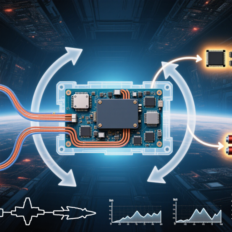
How to Choose an Aerospace Power Converter in 2026?

Define the Mission and Electrical Requirements for 2026

How to Choose an Aerospace Power Converter in 2026?
Define the Mission and Electrical Requirements for 2026

Start with the aircraft or spacecraft mission, not a converter catalog. Record operating duration, startup conditions, duty cycles, and expected service life. A short ground test may not reveal a voltage dip during a cold start. That matters. Note where the unit will sit, too: near a hot engine bay, in a pressurized cabin, or inside an exposed equipment compartment.

Next, map the electrical system in measurable terms. Specify input voltage range, peak and continuous load, output rails, ripple limits, and transient behavior. A 28-volt bus, for example, may sag during motor startup while sensitive sensors need a steady supply. List each load and when it operates. Measure twice. If requirements come from early estimates, mark them as estimates; false precision can lead to the wrong design choice.

Environmental conditions shape the selection just as much. Account for temperature extremes, altitude, vibration, cooling airflow, and electromagnetic compatibility needs. Ask how the converter should respond to overloads or a failed output, and whether backup power is required. Compare efficiency across the actual load range, not only at peak output, because light-load losses can matter during long missions. Keep some margin, but explain why it is needed. Too much margin adds size and weight, and that trade-off deserves another review.

Compare Aerospace Power Converter Architectures and Topologies

How to Choose an Aerospace Power Converter in 2026?
Compare Aerospace Power Converter Architectures and Topologies

Architecture determines how power, heat, and faults move through an aircraft. A centralized converter can simplify maintenance and reduce module count, but concentrates heat and creates a larger failure point. Distributed converters offer modular isolation and shorter motor leads, though they add units, connectors, and control complexity. NASA’s X-57 project documentation describes a 14-motor concept: twelve small propellers for lift and two larger propellers for cruise. It illustrates why converter placement must match the aircraft’s propulsion layout, not just its peak power.

Topology brings a different trade-off. A two-level voltage-source inverter is relatively simple, but switching can increase motor stress and electromagnetic interference. Three-level designs can improve waveform quality and reduce voltage stress on individual devices, at the cost of more components and control demands. SiC devices may support faster switching and compact systems; they also make thermal management and EMI testing less forgiving. The neatest schematic can still hide difficult integration work.

Tips: Compare efficiency across the full load range, not only at peak power. Check altitude insulation, cooling margins, fault isolation, and service access. Test the edges, too. A little uncertainty is useful: early thermal and EMI measurements may challenge assumptions before the architecture is locked. Source: NASA, X-57 Maxwell project documentation.

How to Choose an Aerospace Power Converter in 2026? - Compare Aerospace Power Converter Architectures and Topologies

Architecture or topology Typical conversion Key strengths Main trade-offs Common aerospace applications Selection considerations
Three-phase active front end (AFE) Three-phase AC to regulated DC; often includes input power-factor correction Can control input current and DC-bus voltage; supports bidirectional power flow when designed for it More control, switching, and protection complexity than a passive rectifier; switching can introduce conducted and radiated emissions Generating-system interfaces, high-power DC links, and systems that must return energy to the source Check the aircraft AC frequency range, input distortion limits, transient requirements, regeneration needs, and filter mass
Vienna rectifier Three-phase AC to a unidirectional, split DC bus Three-level switching can reduce device voltage stress and input-current distortion; useful where reverse power flow is not required Does not normally provide bidirectional power flow; split-bus balancing and control add design constraints High-power rectification for DC distribution and onboard equipment Confirm that one-way power conversion is acceptable and evaluate bus balancing, fault response, and semiconductor derating
Interleaved buck or boost Non-isolated DC-to-DC conversion with multiple phase-shifted switching channels Can reduce input and output ripple; phase sharing distributes current across devices and magnetic components Provides no galvanic isolation; current sharing and transient control require careful implementation Regulation of DC buses, battery interfaces, and point-of-load power stages where isolation is not required Use only when the system grounding and safety architecture permit a non-isolated path; assess fault containment and ripple limits
Phase-shifted full-bridge (PSFB) Isolated DC-to-DC conversion, commonly from a high-voltage DC bus to a lower-voltage bus Transformer provides galvanic isolation; suitable for substantial power levels and a broad range of conversion ratios Circulating current and switching losses can reduce efficiency, especially at light load; transformer and output-filter design affect mass Isolated intermediate buses, equipment power supplies, and battery or actuator interfaces Compare light-load performance, transformer insulation, short-circuit behavior, switching frequency, and cooling requirements
LLC resonant converter Isolated DC-to-DC conversion using a resonant tank and high-frequency transformer Can achieve soft switching over a designed operating region, reducing switching losses and electromagnetic emissions Regulation across a wide input or load range can require a wide frequency range; control and magnetic design are sensitive to operating conditions Compact isolated supplies and regulated bus conversion where the input range is well defined Review gain range, start-up behavior, no-load operation, transformer parasitics, and performance at hot and cold extremes
Dual active bridge (DAB) Isolated, bidirectional DC-to-DC conversion between two DC buses Bidirectional power transfer; high-frequency transformer provides isolation; modular arrangements can support scalable power systems Circulating current and soft-switching range depend on voltage ratio and load; control and protection are comparatively complex Energy storage, battery charging and discharging, and interfaces between DC buses Check the full bus-voltage ratio, reverse-power operating points, thermal margins, and fault isolation strategy
Two-level voltage-source inverter DC to single-phase or three-phase AC Well-established structure with straightforward control; relatively low component count compared with multilevel designs Higher switching ripple and device voltage stress can increase filtering or thermal demands at higher bus voltages Motor drives, actuators, and AC loads supplied from a DC bus Match output voltage, frequency, motor-control needs, switching losses, fault handling, and electromagnetic compatibility requirements
Three-level neutral-point-clamped inverter DC to AC using three voltage levels per phase leg Can reduce output voltage steps and device voltage stress relative to a comparable two-level design More switches and clamping components; neutral-point voltage balance and additional failure modes require attention Higher-voltage motor drives and power conversion where waveform quality or device stress is a priority Weigh output filtering and switching benefits against component count, control complexity, and maintainability
Modular multilevel converter (MMC) Modular conversion between DC and AC using series-connected submodules Scalable voltage capability and modular construction; can produce low-distortion waveforms at suitable power levels Many submodules, sensors, and controls increase system complexity; size and component count may be excessive for smaller loads High-power conversion and specialized propulsion or energy-system applications Consider only when voltage and power scale justify the modular approach; assess redundancy, submodule balancing, and maintenance access

Selection note: Topology-level comparisons are indicative, not guaranteed performance values. Final selection should be based on the aircraft bus specification, power and transient profiles, isolation and fault-containment needs, qualification requirements, cooling, electromagnetic compatibility, mass, and maintainability. Representative aircraft electrical systems include 115/200 V, 400 Hz AC and 28 V DC; actual interfaces and limits depend on the aircraft and equipment specification.

Assess Efficiency, Thermal Limits, Size, and Environmental Tolerance

Choosing an aerospace power converter in 2026 starts with the real load profile, not a headline efficiency figure. Compare efficiency across expected input voltages and loads, including startup and brief peak demand. A converter that performs well at one operating point may waste more energy elsewhere. Small margins matter.

Thermal limits need equal attention. Estimate heat at the highest sustained load, then check how the unit handles the aircraft’s actual cooling path and ambient temperature. A compact enclosure can restrict airflow, while nearby equipment may add heat. Review derating curves and temperature limits rather than relying on a single maximum rating. Heat still wins. If testing is possible, measure temperatures under representative conditions; models can miss awkward installation details.

Size and environmental tolerance must work together. Check the converter’s dimensions, mass, mounting points, and cable clearances against the available bay, not just the drawing. Then verify its specified resistance to vibration, shock, humidity, and temperature cycling for the intended installation. Ask what test conditions support each rating, and confirm that system-level qualification covers the installed configuration. These checks take time. It is tempting to choose the lightest unit, but a small weight saving may bring tighter thermal margins or more demanding integration. I would revisit that tradeoff after reviewing the actual mission profile.

Verify Safety, Reliability, and Qualification Requirements

How to Choose an Aerospace Power Converter in 2026?

Verify Safety, Reliability, and Qualification Requirements

When selecting an aerospace power converter, start with the aircraft or spacecraft’s actual operating conditions. Check input-voltage range, load transients, startup behavior, and available cooling. Review thermal limits alongside vibration and shock requirements; a unit that works on a bench may behave differently inside a tightly packed equipment bay. Small details matter.

For safety, examine protection features, insulation design, fault behavior, and the evidence supporting each claim. Confirm that qualification data applies to the exact configuration, including connectors, coatings, and operating temperature range. A certificate alone may not answer every integration question. Ask for test reports, traceability records, and clear change-control information.

Tips: Compare derating curves at your real ambient temperature. Check connector pin assignments before integration. Keep qualification documents with the hardware record.

Reliability depends on more than rated lifetime. Look for environmental test results, failure-rate assumptions, and maintenance requirements, then compare them with the mission profile. Confirm that electromagnetic compatibility testing reflects the intended installation and nearby equipment. If a requirement is unclear, document the assumption and ask the supplier for evidence. I have seen teams focus on headline efficiency and miss a modest airflow restriction; it is an easy gap to overlook, and worth revisiting during design review.

Select a Converter and Confirm Integration and Lifecycle Support

Choosing an aerospace power converter in 2026 starts with the aircraft’s actual electrical environment, not a headline efficiency figure. Record the input-voltage range, each output rail, peak loads, and startup sequence. A processor may draw little power at idle but create sharp transients during operation. Check thermal limits at the enclosure’s real airflow and ambient temperature. Heat builds quickly in a tightly packed bay. Allow margin for vibration, altitude, and electromagnetic compatibility requirements, then confirm those assumptions with the engineering team.

Integration details can decide whether a suitable converter works reliably in the system. Compare connector pinouts, grounding, cooling paths, mounting points, and telemetry signals against the equipment design. Ask how the unit behaves during input interruptions and load changes. Review test evidence, interface drawings, and configuration records before freezing the design. A mismatch in one control signal can mean a board revision; it is easy to underestimate that risk.

Lifecycle support matters just as much as initial fit. Confirm repair procedures, replacement options, technical-document access, and expected availability of critical components. Ask how design changes are communicated and how units can be traced by revision or lot. Keep qualification records and integration notes where future maintainers can find them. Some assumptions will prove wrong in service planning. That is a reason to document them early, not to pretend the first selection is final.

FAQS

What should I define before choosing an aerospace power converter?

Record mission duration, startup conditions, duty cycles, and expected service life. Note the installation location and its temperature.

Which electrical details should I document?

Specify input voltage, continuous and peak loads, output rails, ripple limits, and transient behavior. List when each load operates. Measure twice.

Why does the load profile matter?

Efficiency can change across input voltages and operating loads. Check startup, light-load periods, and brief peaks, not just maximum output.

How should I assess thermal performance?

Estimate heat at sustained loads and review derating curves at expected ambient temperatures. Check airflow near surrounding equipment. Heat still wins.

What installation details can affect size and weight choices?

Check dimensions, mass, mounting points, and cable clearance in the actual equipment bay. A lighter unit may leave less thermal margin.

Which environmental conditions should I verify?

Match temperature, altitude, vibration, shock, and humidity ratings to the installation. Ask what test conditions support each rating.

What safety and qualification evidence should I request?

Review protection features, insulation design, fault behavior, test reports, and traceability records. Confirm the data covers the exact configuration.

How can I judge reliability for a specific mission?

Compare environmental test results, failure-rate assumptions, and maintenance needs with the mission profile. Confirm electromagnetic compatibility testing reflects nearby equipment. Recheck unclear assumptions.

Conclusion

Choosing an Aerospace Power Converter in 2026 begins with a clear definition of the mission: required input and output ranges, load behavior, operating modes, and available power sources. These requirements help narrow the choice among converter architectures and topologies, each of which involves different trade-offs in conversion performance, complexity, and suitability for the intended application.

The selection process should also assess efficiency, heat dissipation, size, weight, and tolerance to vibration, temperature variation, and other environmental conditions. Safety, reliability, and applicable qualification requirements must be verified before a design is approved. Finally, confirm that the converter can integrate with the wider electrical system and that documentation, maintenance, and lifecycle support meet long-term needs. A structured evaluation helps identify an Aerospace Power Converter that fits both mission demands and practical installation constraints.


Seraphina

Seraphina

Seraphina is a dedicated marketing professional with a deep understanding of the company’s products, services, and customer-focused solutions. With strong expertise in market research, content strategy, brand communication, and digital engagement, she regularly contributes insightful articles to......