Choosing the 2026 best Shipboard Backplane System requires more than comparing slot counts or purchase prices. UNCTAD’s Review of Maritime Transport 2024 states that over 80% of global merchandise trade moves by sea. That scale places unusual pressure on onboard control, navigation, and communication hardware. A backplane failure can interrupt data paths, isolate critical modules, and complicate maintenance far from port.
DNV’s Maritime Forecast to 2050 highlights digitalization, alternative fuels, and stricter efficiency demands across shipping. These trends increase the need for high-speed signal integrity, scalable architectures, and dependable thermal management. The right Shipboard Backplane System should support redundancy, vibration resistance, electromagnetic compatibility, and long service intervals. It should also align with applicable marine standards, including IEC 60092 requirements, while fitting the vessel’s classification and integration strategy.
The stakes are physical. Small failures spread. A poorly selected connector, insufficient airflow path, or weak power-distribution design may remain invisible during dockside testing. At sea, heat, salt, shock, and restricted access expose those weaknesses quickly. Allianz’s Safety and Shipping Review 2024 also reinforces the industry’s continuing concern with operational resilience and technology-related risks. Still, no universal winner exists. A highly modular system may add cost, weight, or configuration effort. A compact design may limit future expansion. This guide examines those trade-offs using practical engineering criteria, supplier evidence, and lifecycle thinking. Some assumptions will need reconsideration, because the best solution depends on mission profile, vessel age, crew capability, and integration risk.
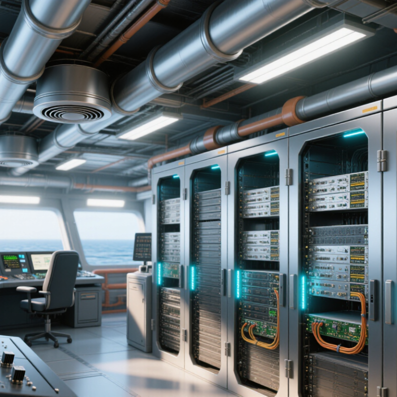
A shipboard backplane system is more than an internal circuit board holder. It serves as the cabinet’s electrical and mechanical foundation. The backplane connects processing, power, communication, and monitoring modules through controlled pathways. In a compact control cabinet, boards slide into fixed slots beside cooling channels and cable guides. This arrangement reduces loose wiring and makes maintenance more predictable. It also supports modular replacement during tight service windows.
Its role begins with reliable power distribution. The design must manage voltage drops, contact resistance, and fault isolation. High-speed data paths require careful routing, shielding, and signal integrity checks. Vibration, humidity, salt exposure, and repeated temperature changes can weaken connectors over time. Therefore, engineers should examine retention strength, corrosion protection, thermal performance, and electromagnetic compatibility evidence. Classification requirements and documented test results should guide the decision.
Field experience shows that accessibility matters as much as electrical performance. A technician should identify a failed module without removing half the cabinet. Clear slot markings and tool-friendly extraction points help. They save time. Redundancy may also be necessary for navigation, propulsion support, or alarm functions. However, adding more connections can increase failure points. No design is perfect. A backplane that looks efficient on a drawing may become difficult to cool or inspect. Reviewing real maintenance scenarios can reveal these weaknesses before installation.
A shipboard backplane must carry power and data through vibration, heat, salt air, and limited space. Practical integration work shows that electrical margins often decide reliability. Specify voltage, current, signal speed, grounding, and fault isolation before selecting connectors or modules. IEC 60092-504 stresses protection against shock, fire, and harsh marine conditions. A small contact-resistance increase can become serious during continuous high-load operation.
Mechanical fit matters just as much. Measure enclosure depth, service access, mounting tolerance, and cable-bend radius onboard. Vibration testing should reflect real engine and propulsion frequencies, not only a laboratory profile. The International Maritime Organization’s Fourth GHG Study reports that shipping produced about 2.89% of global greenhouse-gas emissions in 2018. That figure strengthens the case for efficient power distribution and easier equipment upgrades. However, efficiency alone is not enough. A compact system that cannot be repaired quickly may create greater operational risk.
Environmental screening should include humidity, condensation, salt mist, shock, electromagnetic interference, and temperature cycling. UNCTAD’s Review of Maritime Transport 2024 confirms that over 80% of global merchandise trade by volume moves by sea, leaving little tolerance for avoidable downtime. Use documented test evidence, traceable materials, and conservative derating. Do not trust a perfect spreadsheet. Real vessels rarely behave perfectly. A missed grounding path or blocked airflow can defeat an otherwise strong design. That assumption deserves challenge.
How to Choose the 2026 Best Shipboard Backplane System
A shipboard backplane must match mission data, power limits, and maintenance practices. The architecture shapes every later decision. A centralized backplane offers short paths and predictable timing. It suits compact systems with stable processing roles. However, one damaged segment can affect several modules. That weakness deserves serious attention.
A distributed architecture separates functions across independent nodes. It can improve fault containment and simplify future upgrades. The tradeoff is added cabling, switching logic, and synchronization work. Switched fabrics provide high bandwidth for radar, imaging, and real-time sensor streams. PCIe delivers low-latency board communication, while Ethernet offers flexible routing and mature diagnostics. SpaceWire remains useful where deterministic spacecraft-style links and lightweight protocols matter. CAN can support slower control and monitoring tasks. Do not select a standard from bandwidth figures alone.
Physical integration is equally important. Check contact resistance, vibration tolerance, salt-air protection, thermal paths, and insertion cycles. A rugged connector may still fail if cooling relies on an unrealistic airflow model. I have seen designs pass laboratory tests but struggle after repeated thermal transitions. That result is uncomfortable, yet valuable. Test latency under congestion, not only during clean traffic. Verify fault isolation by removing one module at a time. Keep interoperability evidence, timing measurements, and compliance records available for independent review. A slightly slower architecture may prove more dependable at sea.
Comparison of representative backplane architectures and interconnection standards by theoretical one-way payload bandwidth.
Serial switched-fabric backplanes provide substantially higher point-to-point bandwidth and easier scalability than legacy shared parallel buses. Values are theoretical maximums calculated from published signaling rates, encoding efficiency, and an eight-lane link configuration; practical throughput depends on protocol overhead, topology, connector design, thermal limits, and system software.
Selecting the 2026 best shipboard backplane system starts with evidence, not a feature list. In dockside inspections, I look for stable data paths during vibration, heat, and power variation. Ask for test records covering shock, salt mist, humidity, and electromagnetic interference. A backplane should preserve communication when one module is removed. That detail matters. Check connector retention and contact plating. A loose contact can create intermittent faults that are difficult to reproduce.
Safety needs more than an alarm on a screen. Review electrical isolation, grounding provisions, short-circuit protection, and safe power-down behavior. The system should expose fault conditions without encouraging unsafe access. Clear labeling helps technicians work inside cramped cabinets. Verify that firmware updates include access controls and rollback options. Documentation should identify limits, inspection intervals, and approved replacement procedures. Vague instructions are a maintenance risk.
Maintenance performance is measurable. Compare mean time to repair, spare-module requirements, diagnostic logs, and tool access. Prefer modules that can be exchanged without disturbing adjacent wiring. Confirm whether crews can test a channel while essential services remain active. Ask how long support materials remain available. A low purchase price can hide expensive training and downtime. I would not accept a perfect reliability claim; field conditions are messier than laboratory tests. Even a careful evaluation can miss corrosion under a shield or a connector damaged during installation. Leave room for inspection findings, crew feedback, and design changes after sea trials.
| Evaluation Dimension | Passive Industrial Backplane | CompactPCI Serial Backplane | VPX Rugged Backplane | Custom Rugged Backplane |
|---|---|---|---|---|
| Typical Shipboard Use | Distributed I/O, alarm panels, power monitoring, and non-mission-critical control equipment. | Industrial computers, vessel-management systems, data acquisition, and supervisory control. | High-performance radar processing, sonar, navigation fusion, communications, and mission computing. | Dedicated control, propulsion, power-conversion, or safety systems with fixed interface requirements. |
| System Architecture | Passive common bus or point-to-point wiring; active functions are located on plug-in modules. | High-speed serial point-to-point fabric with centralized system management options. | High-speed switched fabric with options for centralized or distributed management and multiple fabric planes. | Application-specific topology optimized for the required signals, power paths, and redundancy scheme. |
| Typical Data Interfaces | Low- to medium-speed digital I/O, serial links, CAN, Ethernet, and discrete signals. | PCI Express, Ethernet, Serial RapidIO, and other serial communications defined by the system design. | PCI Express, Ethernet, serial fabrics, high-speed serial links, and processor-to-processor interconnects. | Defined by the project; may combine Ethernet, CAN, RS-422/485, fiber, discrete I/O, and proprietary interfaces. |
| Mechanical Robustness | Good when secured in a marine enclosure; connector retention and board support must be verified separately. | High when using card guides, injector/ejector hardware, rear transition support, and locking connectors. | Very high when using conduction cooling, wedgelocks, stiffeners, and reinforced chassis construction. | Can be optimized for the vessel location, but structural performance depends entirely on the engineering design. |
| Temperature Design Target | Commonly 0°C to +55°C for protected equipment spaces; wider ranges require qualified components. | Typically -40°C to +85°C at the component or board level when industrial or ruggedized parts are selected. | Typically -40°C to +85°C at the board or module level, with enclosure thermal analysis required. | Defined by the vessel zone and equipment specification; thermal qualification is project-specific. |
| Shock and Vibration Verification | Requires enclosure-level testing; suitable test methods include IEC 60068-2-6 for vibration and IEC 60068-2-27 for shock. | Usually verified as a complete chassis assembly because connector retention and card support affect performance. | Designed for demanding shock and vibration environments; the complete chassis, payload, and mounting system still require qualification. | Can be tailored to the vessel’s measured vibration spectrum and mounting arrangement, but requires a dedicated test plan. |
| Marine EMC Basis | Must be integrated and tested as part of the final equipment against the applicable marine EMC requirements, including IEC 60533 where applicable. | Requires system-level emissions, immunity, bonding, and cable-shield verification in the installed configuration. | Requires careful high-speed signal integrity, grounding, shielding, filtering, and chassis-level EMC verification. | EMC performance can be optimized for the application, but there is no automatic compliance without formal testing. |
| Safety and Isolation | Simple passive routing reduces active failure points; creepage, clearance, protective bonding, and circuit separation remain essential. | Supports segregated power and signal areas, but isolation is determined by the power supplies, I/O modules, and system wiring. | Supports redundant power and controlled signal domains; high-density layouts require detailed thermal, insulation, and fault-current analysis. | Best option for dedicated galvanic isolation, safe-state circuits, interlocks, and separation of safety-related functions. |
| Power Redundancy | Usually implemented through dual feeds, fused branches, or redundant external power modules. | Can support redundant system slots and dual power entry, subject to chassis and power-supply design. | Strong support for dual or N+1 power architectures, current monitoring, and controlled power sequencing. | Can be purpose-built for dual, 2N, or N+1 power paths with selective protection and fail-safe behavior. |
| Single-Point-Failure Control | Good for simple systems; a shared bus or common connector can still become a single failure point. | Improved through redundant fabrics and system-management controllers, if implemented and tested. | Very good potential through redundant fabrics, independent power domains, and hot-swappable field-replaceable units. | Depends on the fault-tree analysis; redundancy can be optimized, but poor custom design may increase risk. |
| Cooling and Thermal Management | Often relies on enclosure airflow and natural convection; low power density is an advantage. | Forced-air cooling is common for higher-power systems; airflow paths and filter maintenance must be planned. | Conduction cooling is suitable for sealed environments; chassis heat paths and thermal interface materials require inspection. | Can use natural convection, forced air, liquid cooling, or conduction cooling according to the installation constraints. |
| Maintenance Method | Simple troubleshooting and low-cost module replacement; power may need to be removed before servicing. | Supports modular replacement and structured diagnostics; hot-swap capability depends on the power and software design. | Best suited to line-replaceable units, health monitoring, and controlled hot-swap procedures when properly engineered. | Maintenance can be highly efficient when standardized, but unique parts may increase training and spares requirements. |
| Built-In Diagnostics | Usually limited to module-level status indicators and external controller diagnostics. | Can provide system-management telemetry, voltage monitoring, temperature data, and event logging. | Typically supports extensive health monitoring, built-in test, fault isolation, temperature sensing, and power telemetry. | Can be designed around vessel-specific alarms, trend logging, remote diagnostics, and condition-based maintenance. |
| Ingress Protection | Backplane assemblies are generally installed inside a separately rated enclosure; the backplane itself does not establish an IP rating. | Normally requires a sealed or protected chassis to achieve the required enclosure rating. | Often paired with sealed conduction-cooled enclosures; the final IP rating applies to the complete enclosure assembly. | Can be integrated into an enclosure designed for the required IP rating, cable glands, connectors, and service access. |
| Standards and Approval Basis | Typical verification may reference IEC 60092-504, IEC 60533, IEC 60945, IACS UR E10, and applicable class rules. | Uses the same marine installation standards, with additional verification for high-speed interconnects and system integration. | Uses marine environmental and EMC requirements together with detailed platform-level shock, vibration, thermal, and safety testing. | Approval basis must be defined in the procurement specification and agreed with the applicable flag, class, or vessel authority. |
| Relative Reliability Fit | 3 / 5 Strong for low-complexity, low-power systems with few active dependencies. |
4 / 5 Good balance of modularity, performance, and serviceability. |
5 / 5 Best potential for demanding computing and redundant mission systems when fully qualified. |
4 / 5 Can be excellent, but reliability depends heavily on design maturity and production controls. |
| Relative Safety Fit | 4 / 5 Low active complexity supports predictable failure behavior. |
4 / 5 Good isolation and redundancy options with disciplined system integration. |
4 / 5 Strong monitoring and redundancy potential, offset by higher design complexity. |
5 / 5 Best when dedicated safe-state, isolation, and interlock requirements dominate. |
| Relative Maintenance Fit | 4 / 5 Simple replacement and troubleshooting, but limited online service capability. |
4 / 5 Modular servicing and diagnostics are available with appropriate system design. |
5 / 5 Excellent for line-replaceable units and predictive maintenance programs. |
3 / 5 Maintenance can be optimized, but custom parts may extend repair and training requirements. |
| Best Selection Scenario | Choose when the system is simple, cost-sensitive, space is available, and high-speed processing is not required. | Choose when modular computing, moderate-to-high throughput, long service life, and maintainability must be balanced. | Choose when mission performance, high availability, ruggedization, and advanced diagnostics justify higher engineering complexity. | Choose when the system has unusual interfaces, strict safety functions, special mechanical constraints, or a fixed long-term platform design. |
| Selection note: The ratings are comparative design guidance rather than certification claims. Final acceptance should be based on the complete installed equipment, including chassis, connectors, power supplies, cabling, software, mounting, thermal management, and the applicable vessel or class requirements. Marine compliance is established through documented design review and qualification testing, not by the backplane architecture alone. | ||||
Selecting the best shipboard backplane system for a 2026 application begins with the vessel’s mission, not a fashionable data rate. UNCTAD’s Review of Maritime Transport reports that over 80% of global merchandise trade moves by sea. That dependence makes communication downtime expensive. A naval patrol vessel, offshore support ship, and autonomous cargo ship need different architectures.
During sea trials, engineers should measure vibration, shock, salt exposure, heat, and electromagnetic noise at the actual installation point. IEC 60092 guidance supports marine electrical design, while classification rules from DNV emphasize dependable operation under harsh conditions. Choose a backplane with suitable redundancy, controlled impedance, hot-swap capability, and clear fault isolation. Thermal design matters too. A sealed cabinet beside a propulsion converter can become an oven after hours of operation. It needs airflow planning, temperature monitoring, and realistic derating.
Check the numbers carefully. The International Maritime Organization’s 2023 strategy targets net-zero greenhouse-gas emissions from international shipping by or around 2050. Electrification, sensors, and energy-management systems will increase onboard data traffic. However, maximum bandwidth is not always the best answer. It may add heat, cost, and unnecessary complexity. A practical design may combine high-speed links for navigation data with slower, isolated channels for monitoring. That compromise deserves testing.
No checklist is perfect. Engineers sometimes overlook connector access during maintenance. A technician working in a narrow machinery space cannot treat laboratory conditions as reality. Field feedback, documented failure modes, lifecycle support, and independent compliance evidence should influence the final selection.
Start with the vessel’s mission, data patterns, power limits, and maintenance access. Maximum bandwidth is not automatically the best choice.
It suits compact systems with stable processing roles and short communication paths. Timing stays predictable. One damaged segment can affect several modules.
Independent nodes can contain faults and simplify future upgrades. The tradeoff includes extra cabling, switching logic, and synchronization work.
Switched fabrics suit radar, imaging, navigation, and real-time sensor streams. Test congestion behavior, not only clean traffic.
Yes. Low-speed channels can handle monitoring and control tasks. Separating them may reduce heat, cost, and unnecessary complexity.
Test vibration, shock, salt exposure, heat, electromagnetic noise, and repeated insertion cycles. Laboratory success may not predict machinery-space performance.
Model airflow honestly and monitor temperatures near hot equipment. A sealed cabinet beside a propulsion converter can become an oven.
Remove one module at a time and observe system behavior. Record timing, recovery, and affected functions. Small failures reveal large weaknesses.
Check connector access, technician clearance, and replacement procedures. A narrow machinery space changes the design reality.
Keep interoperability records, timing measurements, failure modes, thermal results, and independent compliance evidence. No checklist catches everything.
Choosing the right Shipboard Backplane System for 2026 begins with understanding its role in connecting computing, control, communication, and power-related modules within a vessel. The system should support efficient data exchange, modular expansion, and stable operation while fitting the ship’s mission, architecture, and long-term modernization plans. Selection must consider electrical performance, mechanical integration, thermal management, vibration, humidity, salt exposure, electromagnetic compatibility, and available installation space.
A careful comparison of backplane architectures and interconnection standards can reveal differences in bandwidth, scalability, serviceability, and compatibility with existing equipment. Reliability and safety are equally important, requiring robust materials, secure connections, fault isolation, predictable cooling, and clear maintenance access. The best solution is therefore not simply the highest-performance option, but the one that balances lifecycle cost, operational reliability, environmental resistance, future upgrade potential, and crew-maintenance needs for the specific 2026 shipboard application.